Physics • Year 12 • Module 6 • Lesson 8
Forces Between Parallel Conductors
Lock in the core vocabulary, the force-per-unit-length formula, and the attraction/repulsion direction rule before tackling calculations.
1. Term–definition match
In the right-hand column write the matching term from the list below. Force per unit length · Permeability of free space (μ0) · Ampere (SI definition) · Motor effect · Attraction · Repulsion · Right-hand grip rule · Parallel conductors · Newton per metre (N/m) · Magnetic flux density. 10 marks (1 each)
| # | Definition | Matching term |
|---|---|---|
| 1.1 | The force between two long straight wires divided by their length, measured in N/m. | |
| 1.2 | A fundamental constant equal to 4π × 10−7 T m A−1, appearing in the force law for parallel conductors. | |
| 1.3 | The SI unit of force per unit length between parallel wires. | |
| 1.4 | The current which, maintained in two infinite parallel conductors 1 m apart in vacuum, produces a force of 2 × 10⁻⁷ N per metre. | |
| 1.5 | A rule: point your right thumb in the direction of current; curled fingers give the direction of the surrounding magnetic field. | |
| 1.6 | The force experienced by a current-carrying conductor placed in an external magnetic field; given by F = BIl sinθ. | |
| 1.7 | The force that draws two wires together; occurs when currents flow in the same direction. | |
| 1.8 | The force that pushes two wires apart; occurs when currents flow in opposite directions. | |
| 1.9 | Two wires lying in the same plane and oriented in the same direction (zero divergence between them). | |
| 1.10 | The symbol B; quantifies the strength of a magnetic field at a given point in space. |
2. True or false — with correction
Circle T or F for each statement. If the statement is false, write the corrected version on the line below. 12 marks (1 T/F + 1 correction each)
2.1 Two parallel wires carrying currents in the same direction will attract each other. T / F
2.2 The force per unit length between two parallel wires is inversely proportional to the separation d; halving d doubles F/l. T / F
2.3 The ampere is defined using two wires each carrying 1 A, placed 2 m apart in vacuum, producing a force of 2 × 10⁻⁷ N per metre. T / F
2.4 If both currents in a pair of parallel wires are reversed simultaneously, the force direction changes from attraction to repulsion. T / F
2.5 The permeability of free space μ0 has the exact value 4π × 10−7 N A−2. T / F
2.6 By Newton’s third law, the force that wire 1 exerts on wire 2 is equal in magnitude but opposite in direction to the force that wire 2 exerts on wire 1. T / F
3. Fill-in-the-blank paragraph
Use the word bank to complete the passage. Each word is used once. 8 marks (1 per blank)
Word bank:
ampere · attract · grip · inversely · motor effect · permeability · repel · separation
Each current-carrying wire produces a magnetic field described by the right-hand ___________ rule. The second wire sits in this field and experiences a ___________ force. When both currents flow in the same direction, the wires ___________; when they flow in opposite directions, the wires ___________. The force per unit length is proportional to the product of the two currents and ___________ proportional to the ___________ d. The constant μ0 is called the ___________ of free space, and this relationship is precise enough to define the ___________.
4. Function recall
Answer each question in 1–2 sentences using precise physics terms. 8 marks (2 each)
4.1 State the formula for the force per unit length between two parallel current-carrying conductors and define every symbol, including its SI unit.
4.2 Explain, using the right-hand grip rule, why the magnetic field produced by wire 1 is directed into the page at the location of wire 2 (assuming both wires are side by side with current flowing upward).
4.3 State the SI definition of the ampere in terms of the force between two parallel conductors.
4.4 Identify what happens to the force per unit length if the current in one wire is tripled while all other variables remain constant.
5. Equation mapping — predict the change
Two parallel wires originally experience a force per unit length of F/l. In each row, only one change is made. State the new force per unit length in terms of F/l. 6 marks (1 each)
| Change made (all other variables constant) | New F/l (in terms of F/l) |
|---|---|
| I1 is doubled (I1 → 2I1) | |
| Separation is tripled (d → 3d) | |
| Both currents are halved (I1 → I1/2, I2 → I2/2) | |
| Separation is halved (d → d/2) | |
| I2 is tripled and d is tripled | |
| Current in wire 1 is reversed in direction |
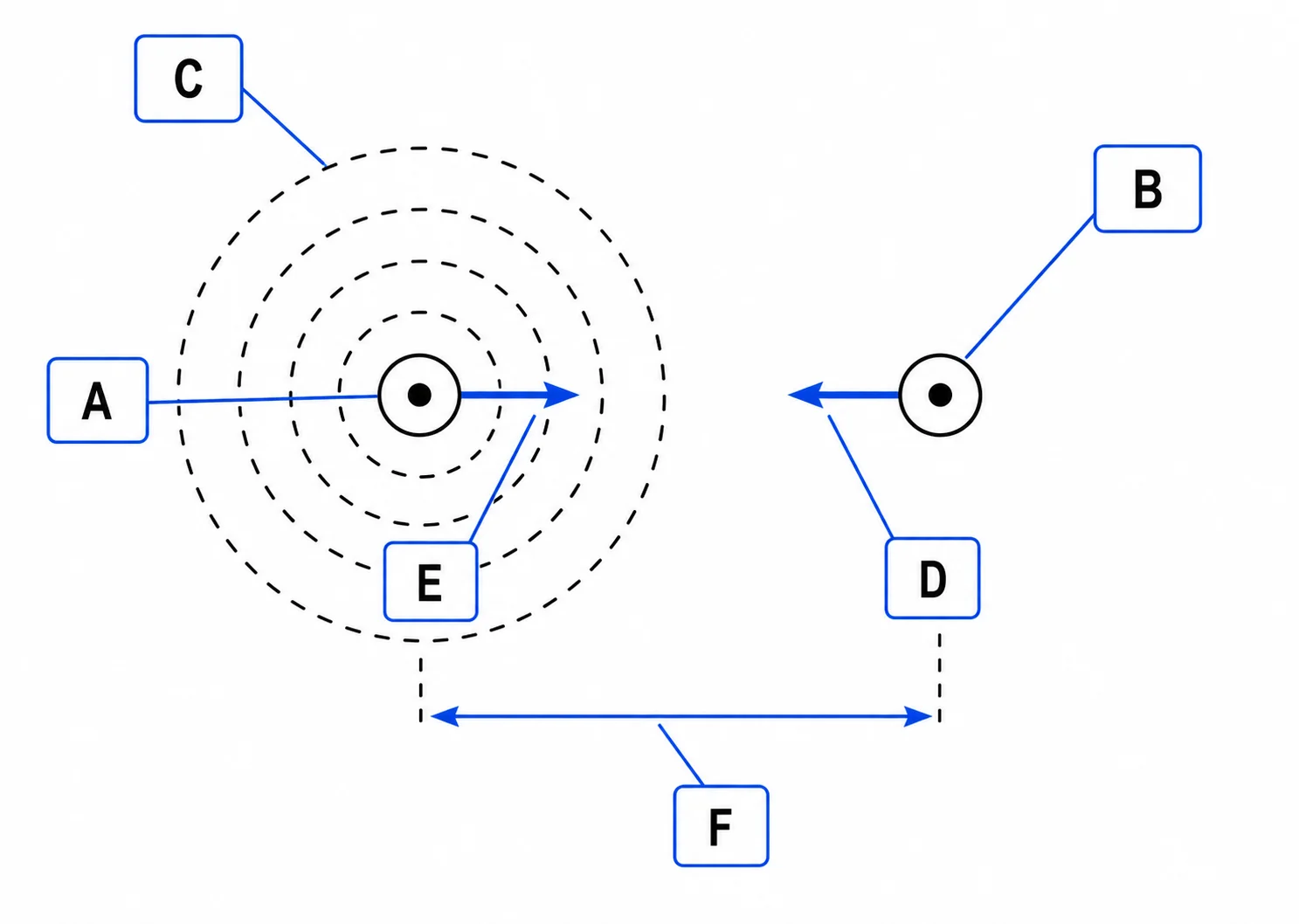
6. Label the parallel-conductor diagram
The diagram below shows two cross-sectional views of parallel wires (dots indicate current out of the page). Label boxes A–F with the correct item from the list: wire 1, wire 2, magnetic field from wire 1, force on wire 2 (direction), force on wire 1 (direction), separation d. 6 marks (1 each)
| Box | Label |
|---|---|
| A | |
| B | |
| C | |
| D | |
| E | |
| F |
Q1 — Term–definition match
1.1 Force per unit length • 1.2 Permeability of free space (μ0) • 1.3 Newton per metre (N/m) • 1.4 Ampere (SI definition) • 1.5 Right-hand grip rule • 1.6 Motor effect • 1.7 Attraction • 1.8 Repulsion • 1.9 Parallel conductors • 1.10 Magnetic flux density.
Q2 — True / false with correction
2.1 True. Same-direction currents attract.
2.2 True. F/l = μ0I1I2 / (2πd); F/l is inversely proportional to d, so halving d doubles F/l.
2.3 False. The ampere is defined using two wires each carrying 1 A placed 1 m apart (not 2 m), producing a force of 2 × 10⁻⁷ N per metre.
2.4 False. Reversing both currents simultaneously means they are still flowing in the same direction relative to each other, so the force remains attractive with the same magnitude. The direction (attraction or repulsion) does not change.
2.5 True.
2.6 True. Newton’s third law applies: the force pairs are equal in magnitude and opposite in direction.
Q3 — Cloze paragraph
In order: grip / motor effect / attract / repel / inversely / separation / permeability / ampere.
Q4.1 — Force per unit length formula
F/l = μ0I1I2 / (2πd). F/l = force per unit length (N/m); μ0 = permeability of free space = 4π × 10−7 T m A−1; I1 and I2 = currents in each wire (A); d = perpendicular separation between the wires (m).
Q4.2 — Right-hand grip rule and field direction
Point your right thumb upward (direction of current in wire 1). Your curled fingers on the right side of wire 1 curl away from you (into the page). At the location of wire 2 (to the right of wire 1), the field from wire 1 therefore points into the page.
Q4.3 — SI definition of the ampere
One ampere is the constant current which, if maintained in two straight parallel conductors of infinite length, of negligible cross-section, placed 1 m apart in vacuum, would produce between them a force equal to 2 × 10⁻⁷ newtons per metre of length.
Q4.4 — Effect of tripling one current
Since F/l is directly proportional to I1 (and to I2), tripling one current triples the force per unit length. The new F/l = 3 × (original F/l).
Q5 — Equation mapping
I1 → 2I1: 2F/l. d → 3d: F/l ÷ 3 = F/3l. Both currents halved: F/l ∝ (I1/2)(I2/2) = I1I2/4, so new value = F/4l. d → d/2: 2F/l. I2 → 3I2 and d → 3d: numerator ×3, denominator ×3, so F/l unchanged. Current in wire 1 reversed: magnitude unchanged at F/l; force direction changes from attraction to repulsion.
Q6 — Parallel conductor diagram labels
A: Wire 1 (left circle, dot = current out of page). B: Wire 2 (right circle, dot = current out of page). C: Magnetic field from wire 1 (dashed concentric circles, anticlockwise when current is out of page). D: Separation d (horizontal bracket between the two wires). E: Force on wire 2 (arrow pointing left, toward wire 1 — attraction). F: Force on wire 1 (arrow pointing right, toward wire 2 — attraction).