Physics • Year 11 • Module 2: Dynamics • Lesson 2
Vector Forces — Resolution and Equilibrium
Apply vector addition, component resolution and equilibrium conditions to data tables, real scenarios and a diagram critique.
1. Interpret component calculation data — V8 Supercar pit push
A race engineer records the push force and angle applied by different pit crew members to move a V8 Supercar. The table below lists six scenarios. 10 marks
| # | Force F (N) | Angle θ above horizontal (°) | Fx = F cos θ (N) | Fy = F sin θ (N) | Resultant magnitude (N) |
|---|---|---|---|---|---|
| 1 | 80 | 0 | |||
| 2 | 80 | 90 | |||
| 3 | 50 | 30 | |||
| 4 | 100 | 60 | |||
| 5 | 120 | 45 | |||
| 6 | 200 | 25 |
1.1 Complete the Fx, Fy, and resultant magnitude columns. Round each answer to 1 decimal place. Show working for rows 3 and 4 in the space below. 6 marks (1 per row)
1.2 Describe the pattern in Fx and Fy as the angle increases from 0° to 90°. Use rows 1–2 to frame your answer. 2 marks
1.3 A crew member claims the resultant magnitude in row 5 is 120 N because “the angle doesn’t change the total force, only its direction.” Evaluate this claim. 2 marks
2. Interpret a tension–angle graph — traffic light suspension
A 25 kg traffic light hangs from two symmetric cables, each at angle θ above the horizontal. A student calculates cable tension T for seven different angles and plots the results below. 7 marks
Figure 2. Calculated cable tension T vs cable angle θ for a 25 kg (W = 245 N) traffic light on two symmetric cables. Formula: T = W / (2 sin θ). Illustrative data.
2.1 Describe the trend in cable tension as the angle increases from 10° to 80°. 2 marks
2.2 Using the formula T = W / (2 sin θ), calculate T at θ = 35° and estimate its position on the graph. Show your working. 2 marks
2.3 A structural engineer says: “We should never hang a cable at less than 20° from the horizontal because the tension becomes dangerously large.” Use the graph and one calculation to justify or refute this claim. 3 marks
3. Compare 1D and 2D force analysis across five criteria
Complete the two-column table. For each feature, write a concise description that distinguishes 1D and 2D analysis. 10 marks (1 per cell)
| Feature | 1D force analysis | 2D force analysis |
|---|---|---|
| Number of directions checked | ||
| Tool used to find resultant | ||
| Equilibrium condition | ||
| Key formula | ||
| Real-world example |
4. Predict and justify — Sydney Harbour Bridge cable tension
The Sydney Harbour Bridge uses diagonal suspender cables to transfer load from the deck to the arch. As a deck panel is added, the vertical load increases. Suppose the cable angle to the horizontal is reduced from 60° to 30° while the load remains constant.
5 marks
4.1 Predict whether the tension in each cable increases, decreases, or stays the same when the angle decreases from 60° to 30°. Justify your prediction using the equilibrium formula T = W / (2 sin θ) and a numerical comparison. Show all working. 3 marks
4.2 A bridge engineer argues that “horizontal cables would be the most efficient because they run in a straight line.” Use physics reasoning to explain why a truly horizontal suspension cable is impossible for a static load. 2 marks
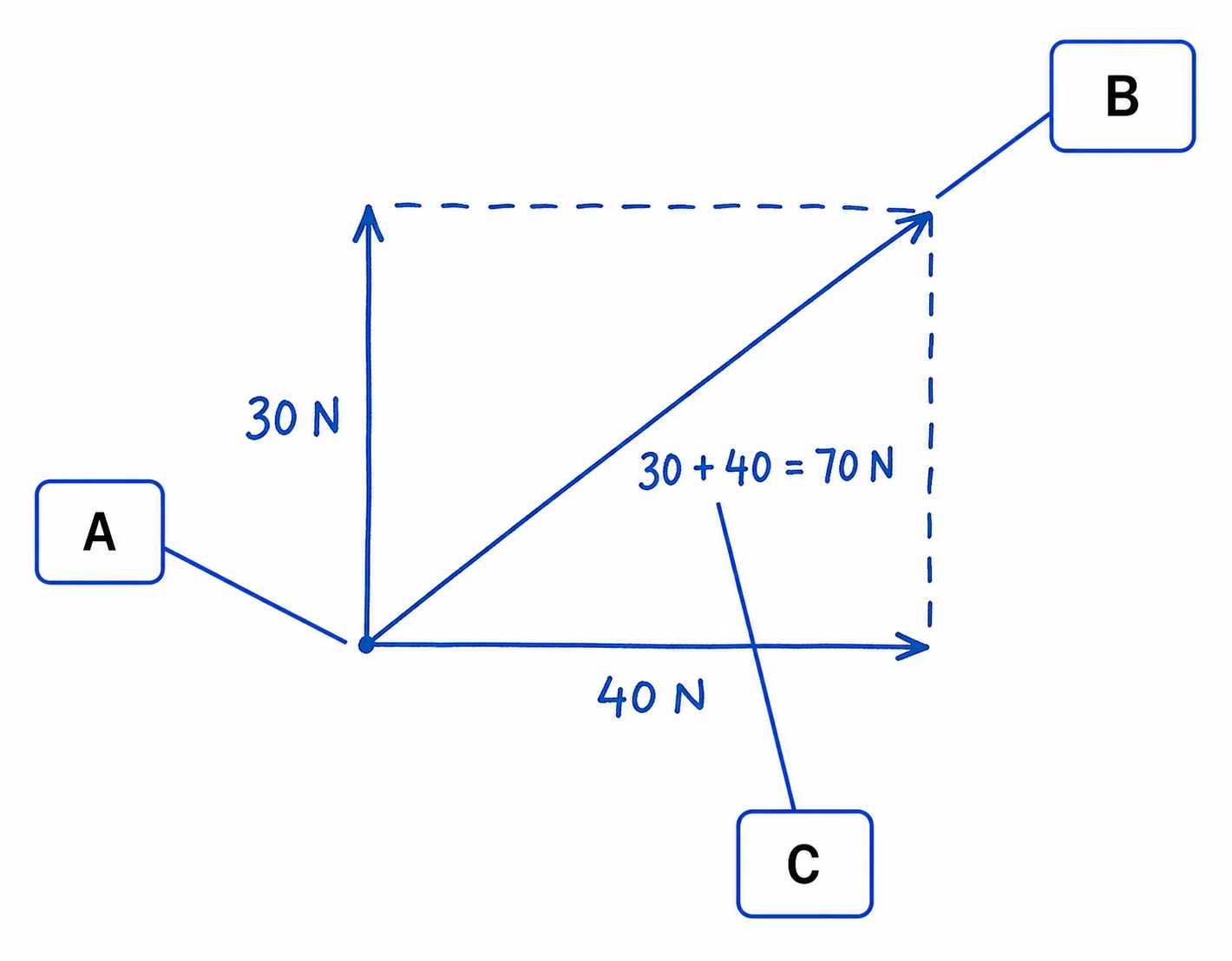
5. Diagram critique — what’s wrong with this student’s vector addition?
A Year 11 student drew the diagram below to show the resultant of two force vectors. There are three errors in the diagram. Identify each error and write the correction. 6 marks (2 per error: 1 identify, 1 correct)
5.1 Error 1: What is wrong with the vector placement?
Correction:
5.2 Error 2: What is wrong with where the resultant arrow is drawn?
Correction:
5.3 Error 3: What is wrong with the resultant magnitude label?
Correction:
Q1.1 — Component calculation table
Row 1 (80 N, 0°): Fx = 80 N; Fy = 0 N; Resultant = 80 N. Row 2 (80 N, 90°): Fx = 0 N; Fy = 80 N; Resultant = 80 N. Row 3 (50 N, 30°): Fx = 50 cos 30° = 43.3 N; Fy = 50 sin 30° = 25.0 N; Resultant = √(43.3² + 25.0²) = √(1875 + 625) = 50 N. Row 4 (100 N, 60°): Fx = 100 cos 60° = 50.0 N; Fy = 100 sin 60° = 86.6 N; Resultant = 100 N. Row 5 (120 N, 45°): Fx = Fy = 120 cos 45° = 84.9 N; Resultant = 120 N. Row 6 (200 N, 25°): Fx = 200 cos 25° = 181.3 N; Fy = 200 sin 25° = 84.5 N; Resultant = 200 N. Note: the resultant always equals the original F because the components come from the same vector.
Q1.2 — Pattern in Fx and Fy (2 marks)
As the angle increases from 0° to 90°, Fx decreases (from the full magnitude F at 0° to 0 at 90°) and Fy increases (from 0 at 0° to the full magnitude F at 90°). The total vector magnitude stays constant; only the distribution between horizontal and vertical components changes [1]. At 0° all force is horizontal; at 90° all force is vertical [1].
Q1.3 — Crew member’s claim (2 marks)
The claim is partially correct but misleading. The total force magnitude is unchanged (still 120 N), so the crew member is right about that [1]. However, the angle determines how much of that force acts in the horizontal direction (useful for moving the car along the ground) vs. the vertical direction (which may be wasted or even reduce traction). At 45°, only 84.9 N acts horizontally; at 0° the full 120 N acts horizontally. So direction matters greatly for the effectiveness of the push, even if the magnitude is unchanged [1].
Q2.1 — Trend in cable tension (2 marks)
As the cable angle increases from 10° to 80°, the tension T decreases rapidly at first (steep drop from ~707 N to ~245 N between 10° and 30°) then more gradually, approaching a minimum near 80° (about 124 N) [1]. The curve is hyperbolic in shape, consistent with T = W / (2 sin θ) — as sin θ increases toward 1, T decreases toward W/2 [1].
Q2.2 — Calculation at θ = 35° (2 marks)
T = W / (2 sin 35°) = 245 / (2 × 0.574) = 245 / 1.148 = 213.4 N [1]. On the graph, this point would lie between the 30° data point (~245 N) and the 40° data point (~190 N), slightly above the midpoint — approximately at the position (35°, 213 N) [1].
Q2.3 — Engineer’s 20° claim (3 marks)
The claim is justified [1]. At θ = 20°: T = 245 / (2 sin 20°) = 245 / (2 × 0.342) = 245 / 0.684 = 358 N. At θ = 10°: T ≈ 707 N [1]. The graph shows a very steep rise in tension below 20°; each degree reduction below 20° causes a much larger tension increase than each degree above 20°. Many structural materials have design limits (e.g. steel cable safe working load); at angles below 20° the tension could easily exceed these limits even for moderate loads, making the claim physically and structurally reasonable [1].
Q3 — 1D vs 2D comparison table
Number of directions checked: 1D: one direction only (along the line of action). 2D: two perpendicular directions (x and y). Tool used to find resultant: 1D: algebraic addition with sign convention. 2D: component resolution then Pythagoras’ theorem: F = √(Fx² + Fy²). Equilibrium condition: 1D: ΣF = 0 (net force in one direction = 0). 2D: ΣFx = 0 AND ΣFy = 0. Key formula: 1D: Fnet = ΣF. 2D: Fx = F cos θ, Fy = F sin θ. Real-world example: 1D: Two people pushing a trolley in opposite directions along the same aisle. 2D: Two ropes holding a traffic light at angles — resolve each rope’s tension into components before checking equilibrium.
Q4.1 — Bridge cable tension prediction (3 marks)
Tension increases when the angle decreases [1]. Using T = W / (2 sin θ) with W = 245 N (for a 25 kg load as an example): at 60°, T = 245/(2×sin 60°) = 245/1.732 = 141 N. At 30°, T = 245/(2×sin 30°) = 245/1.0 = 245 N [1]. The tension nearly doubles because sin 30° = 0.5 is half of sin 60° = 0.866; a shallower cable provides less vertical support per Newton of tension, so a larger tension is required to maintain vertical equilibrium [1].
Q4.2 — Horizontal cable impossibility (2 marks)
A truly horizontal cable (angle = 0°) would have a vertical component of zero: Fy = T sin 0° = 0 [1]. For equilibrium, the vertical components of all cables must sum to equal the weight of the load (ΣFy = W). If Fy = 0, the equilibrium condition (ΣFy = 0) can never be satisfied, meaning an infinite tension would theoretically be required to support any non-zero weight. A horizontal cable provides no vertical support, so it is physically impossible for a static vertical load [1].
Q5 — Diagram critique (6 marks)
5.1 Error 1 (tail-to-tail placement): The student placed both vectors starting from the same point (tail-to-tail) instead of tip-to-tail [1]. Correction: In the tip-to-tail method, the tail of the second vector must be placed at the tip (arrowhead) of the first vector; vectors are chained in sequence, not originating from the same point [1].
5.2 Error 2 (resultant arrow direction): The resultant is drawn from the tip of vector 1 to the tip of vector 2 instead of from the tail of the first vector to the tip of the last vector [1]. Correction: In the tip-to-tail construction, the resultant arrow starts at the tail of the first vector drawn (where the chain begins) and ends at the tip of the last vector drawn (where the chain ends) [1].
5.3 Error 3 (scalar magnitude addition): The student wrote “30 + 40 = 70 N” instead of using Pythagoras’ theorem for perpendicular forces [1]. Correction: For two forces at 90° to each other, the resultant magnitude = √(30² + 40²) = √(900 + 1600) = √2500 = 50 N. Scalar addition of force magnitudes only applies when the forces act in exactly the same direction [1].